Construction
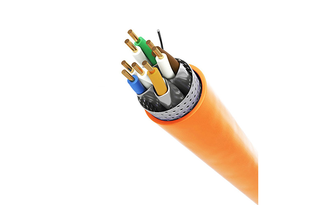
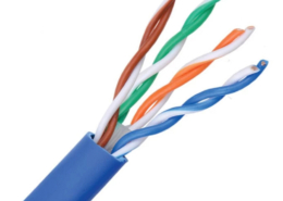
Solid bare copper conductors insulated with thermoplastics polyolefin. Two insulated conductors twisted together to form a pair and four such pairs cabled to form the basic unit. A cross filler is cabled in between to separate the 4 pairs insulated conductors . Aluminum Polyester Tape and tinned copper braiding overall the 4pairs .Overall jacket with PVC, LSZH, PE compound.
Standard Compliances
ISO/IEC 11801:2011(Ed.2.2)
IEC 61156-5:2009(Ed.2.0)
EN 50173-1:2011
EN 50173-2:2007 including amendment A1:2010
ANSI/TIA-568-C.2:2009
Applications
IEEE 802.3: 1000BASE-T (Gigabit Ethernet), 100BASE-TX, 10BASE-T
ANSI/TIA/EIA-854: 1000BASE-TX
155 Mb/s, 1.2 Gb/s ATM
ANSI X3.263: 100 Mb/s
IEEE 802.3af DTE Power (POE)
4/16 Mb/s Token Ring
Digital Video
Broadband and Baseband Analog Video
Cable Description
| Conductor |
| Size |
24 AWG |
| Type |
Solid bare copper |
| Diameter (mm) |
0.55± 0.01 |
| Insulation |
| Type |
PE |
| Diameter (mm) |
1.13± 0.05 |
| Min. thickness (mm) |
0.26 |
| Pairs with color code |
| Pair 1 |
Blue / White – blue strip |
| Pair 2 |
Orange / White – orange strip |
| Pair 3 |
Green / White – green strip |
| Pair 4 |
Brown / White – brown strip |
| Central Element |
| Type |
PE cross separator |
| Jacket |
| Type |
PVC, LSZH, PE |
| Overall Diameter (mm) |
7.29 ± 0.3 |
| Shield |
| TPYE (Overall shielded) |
Polyester Tape |
| TPYE (Overall shielded) |
Aluminum Polyester Tape |
| Tinned copper drain wire(mm) |
0.495 ± 0.008 |
| Type (Overall braiding) |
Tinned Copper 40% to 60% Braiding |
| Cold bend test |
-20 ± 2℃ X 4hrs no. crack |
| Dielectric strength |
AC 1.7 KV for 2S. |
| Insulation |
Before Aging |
After aging |
| Min. Tension strength (psi) |
2400 |
75% before aging (100℃ X 48hrs) |
| Min elongation (%) |
300 |
75% before aging (100℃ X 48hrs) |
| Jacket |
|
|
| Min. Tension strength (psi) |
2000 |
75% before aging (100℃ X 168hrs) |
| Min elongation (%) |
100 |
50% before aging (100℃ X 168hrs) |
| Min. bending radius (mm) |
60 |
| Max. pulling tension (Ibs) |
25 |
| Installation temperature |
-10℃ to +60℃ |
| Operating temperature |
-10℃ to +60℃ |
Technical Data- Physical
Technical Data – Electrical
| Conductor resistance (Ω/100m @ 20℃) |
Max. |
9.5 |
| DC resistance unbalance (%) |
Max. |
4 |
| Pair-to-ground capacitance unbalance (pF/km) |
Max. |
1600 |
| Delay skew (ns/100m) |
Max. |
45 |
4 ≦ f ≦ 250MHz |
| Insertion Loss (dB/100m) |
Max. |
1.82*√f + 0.0169* f +0.25/√f |
4 ≦ f ≦ 250MHz |
| Pair to Pair NEXT (dB/100m) |
Min. |
75.3 – 15 * log(f) |
4 ≦ f ≦ 250MHz |
| PowerSum pr-pr NEXT (dB/100m) |
Min. |
72.3 – 15 * log(f) |
4 ≦ f ≦ 250MHz |
| ELFEXT (dB/100m) |
Min. |
68 – 20 * log(f) |
4 ≦ f ≦ 250MHz |
| PowerSum ELFEXT (dB/100m) |
Min. |
65 – 20 * log(f) |
4 ≦ f ≦ 250MHz |
| Return Loss (dB) |
Min. |
20 + 5 * log(f) |
1 ≦ f <10MHz |
|
|
25 |
10 ≦ f <20MHz |
|
|
25 – 7 * log(f / 20) |
20 ≦ f ≦250MHz |
| Propagation Delay (ns/100m) |
Max. |
534 + 36 /√f |
4 ≦ f ≦ 250MHz |
| Input Impedance (Ω) |
|
100 ± 15% |
1 ≦ f ≦ 100MHz |
|
|
100 ± 22% |
100<f≦ 250MHz |
| IEC 61156-5 ed2.0 Category 6 horizontal cable parameters |
|
Freq.
(MHz)
|
Ins. Loss
(dB/100m) |
RL
(dB) |
Pair to Pair |
Power Sum |
Po. Delay
(ns/100) |
| NEXT |
ELFEXT |
NEXT |
ELFEXT |
| (dB/100m) |
(dB/100m) |
|
Max. |
Min. |
Min. |
Min. |
Min. |
Min. |
Max. |
| 1 |
— |
20 |
— |
— |
— |
— |
— |
| 4 |
3.8 |
23 |
66.3 |
56.0 |
63.3 |
53.0 |
552.0 |
| 10 |
6.0 |
25 |
60.3 |
48.0 |
57.3 |
45.0 |
545.4 |
| 16 |
7.6 |
25 |
57.2 |
43.9 |
54.2 |
40.9 |
543.0 |
| 20 |
8.5 |
25 |
55.8 |
42.0 |
52.8 |
39.0 |
542.0 |
| 31.25 |
10.7 |
23.6 |
52.9 |
38.1 |
49.9 |
35.1 |
540.4 |
| 62.5 |
15.5 |
21.5 |
48.4 |
32.1 |
45.4 |
29.1 |
538.6 |
| 100 |
19.9 |
20.1 |
45.3 |
28.0 |
42.3 |
25.0 |
537.6 |
| 200 |
29.1 |
18 |
40.8 |
22.0 |
37.8 |
19.0 |
536.5 |
| 250 |
33.0 |
17.3 |
39.3 |
20.0 |
36.3 |
17.0 |
536.3 |
Note
All electrical characteristics are given at 20℃
All tests include 401 points swept frequency measurements.


